
Power Converters
Our power converters provide reliable power management for critical applications, ensuring uninterrupted supply and peak performance.
Welcome to Trystar’s website! You’ve been redirected here from Oztek Corporation’s site, and we’re excited to introduce you to Oztek’s innovative contributions as part of the Trystar family. Since joining Trystar in 2022, Oztek has expanded our offerings with its cutting-edge power conversion technologies, delivering tailored AC and DC power solutions across various critical industries. From advanced power inverters and high-power density designs to modular converters, Oztek’s solutions complement Trystar’s commitment to resilient and customizable power systems. Our team of skilled experts is ready to support your unique power needs. Explore our site to discover more about our complete suite of power solutions designed to empower your business.
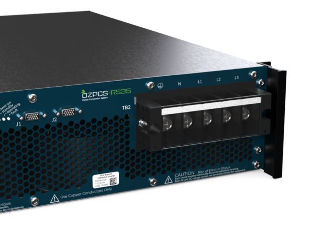
Our battery inverters are designed to provide efficient, high-performance power conversion tailored for various energy storage needs. The RS35 is a 35 kVA inverter offering precision and flexibility in power conversion, perfect for applications demanding reliable backup and load support. For enhanced power capabilities, the RS40 delivers 40 kVA in a compact design, ideal for facilities requiring robust energy management. Meanwhile, the EP40 stands out as an outdoor-rated 40 kVA solution built to withstand challenging environmental conditions, providing dependable power conversion in outdoor and rugged settings. Each of these inverters combines advanced functionality and scalability, ensuring versatile support for both critical and auxiliary power applications.
It’s only the right power solution if you know you can trust the team behind it. As a leader in the engineering and manufacturing of power solutions, ensuring the quality of our products and services is a top priority. Our team members are committed to doing what’s right for your unique situation with products and services you can count on.
Our power converters provide reliable power management for critical applications, ensuring uninterrupted supply and peak performance.

Our SCR driver boards are fully configurable with the Power Studio™ Configuration Tool, a Windows GUI that enables quick and easy setup, operation, and troubleshooting.
Our team is here to support you and solve your power challenges. Connect with our responsive experts today to learn about our customized power solutions and products.